|
|
|
|
|
|
|
|
Abstract
For the automobile Industry, due to the demand of the comfort customers requirements the industry started introducing the entertainment systems like DVD Player, GPS Navigation systems, etc., apart from Radio and Music systems which are very traditional from the past. Now days the customers are using the GPS Navigation along with all type of media entertainment in comfort cars. However the price of the whole system is bit expensive such that all kinds of the customers can�t afford. The customers who are using expensive cars can only able to using these kinds of systems which are coming along with luxurious cars as an accessory. This Master Thesis describes the �Design and Implementation of a Media Entertainment System Running on a Carputer� which plays a major role for all kinds of customers to enjoy the DVD Player, Music Player, Video Player, Radio, TV and GPS Navigation system as a single device in Car. Moreover the cost of the product is not so expensive like the present available systems in the market. The motto behind this thesis is to bring all kinds of entertainment systems along with GPS navigation to all kinds of automobile customers.
Table of Contents
Chapter 1: Overview of Kiebel Computerdienste 1.3 Hardware Development and Reselling Chapter 2: Master Thesis Requirements 4.2.1 Mini P3 Aluminium Car PC 4.3 Peter Bridger a one man company Chapter 5: Software Development Process 5.2.2 Software Chronic Crisis Recognition 5.3 Processes and meta-processes 5.3.1 Capability Maturity Model 5.3.5 Agile Software development 5.4 Software Life Cycle Models 5.4.1 Requirements Engineering 5.5 Software Quality Characteristics Chapter 6: Software Model and Programming Paradigms 6.1.1 Top � Down and Bottom-up Model 6.1.3 Evolutionary Prototyping Model 6.1.4 Iterative and Incremental development 6.2 Aspects of programming paradigms 6.3 Types of programming paradigms 6.3.7 Object oriented programming 6.3.9 Component-oriented programming 7.5.2 Unified Modelling language (UML) 7.7.5 Software Testing Activities 7.8 Delivery and Maintenance Process
Overview of Kiebel Computerdienste Kiebel Computerdienste is a small company located in south of Germany in a city called Willst�tt mainly deals with computer hardware assembling and reselling business. Due to the enormous demands for the software projects, the company has recently launched its potential in the field of software developments to compete with the market challenges of day today software technologies.
The company started as a one man company about 10 years ago dealing with PC assembling only. Later the company has increased their capital to resell all kinds of computer hardware�s, right now raised their flag as �Power Seller� in eBay. Also the company hold online shops to develop their business. The company has more than 1000 customers till today. Recently it focussed its interest in developing palms for Customer Maintenance System with a chip card reader facility; this project�s success motivates the company to develop all kinds of Software Application projects also.
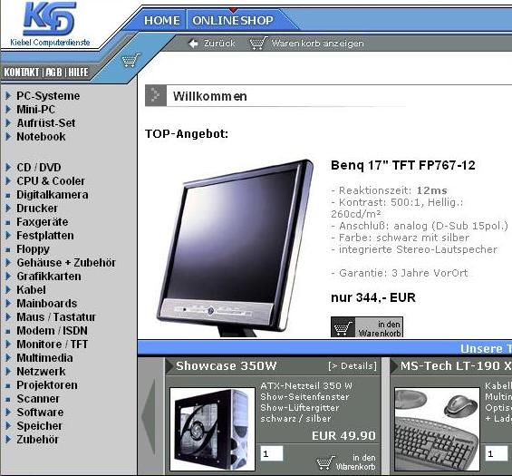
1.3 Hardware Development and Reselling Hardware development includes assembling Desktop PCs and Mini PCs depends upon the customer�s configuration requirements. The latest small PC is about 12 inches height called �Shuttle X� made the customer�s interest towards small PCs. The company holds the dealership for all kinds of �BENQ� products. Reselling of Laptops, Scanners, Printers, Beamers, LCD monitors, Fax machines, Audio & Video systems, Digital Cameras, and all its accessories are the backbone of the company�s business. Its main focus is to produce small PCs with updated configuration at an affordable cost. Now the company deals products like PCs with integrated TV and media entertainment systems also. The company deals both wholesale and retail sale for all the above mentioned products. All the products marketing are done mainly via online shop and also through the online store eBay. The below figure shows the website of the company and how it deals with the product sales through online shops.
Figure 1 : Kiebel Computerdienste Web profile
The hardware demands from the customers forced the company to turn their direction towards software developments also. The first software project is the Palm with chip card reader facility for Customer Maintenance System used in various clubs and discos to identify their customers with the help of photograph. This system has a server contains all the information about the customers including their photographs. When the palm reads the chip card, the palm will communicate with the server to identify their customer. The whole project has been done in Delphi 7 and SQL server. Apart from Application projects the company deals web related projects also for online shops using PHP scripts and HTML.
Later on developing mini PCs and tablet PCs raised �Why not a computer in Car?� which invent a very small computer inside the dashboard of a car like present music systems available. The main idea is to fix the computer unit and the 7 inch monitor such that it sits perfectly in the slot provided for the music system in car dashboard. The idea of implementing an integrated TV and Radio systems with an antenna is an added advantage of this product. The ideas about the user interface and the entertainment systems to be included in the software for the above mentioned unit evolved this Master Thesis. The detailed overview of this Master Thesis will be discussed in chapter 2. The company will launch the product under the name �CARPUTER� since the car dashboard has a computer unit inside.
As Automobile industry is the growing business in Germany, automobile manufacturers are always trying to improve the quality of the product by improving the testing procedures of almost every part of the automobile. The manufacturers also introduce attractive entertainment system and luxurious accessories in the present cars before delivering it to the customers. The motto behind the process is to keep hold the customers firm and tight with the company product. Only luxurious category cars can able to avail most of the privileges. For example BMW 7 series cars have a good entertainment system with a 7 inch display in dashboard along with GPS Navigation system. Normal small cars should use GPS Navigation system as a separate device in car, same holds well for the entertainment system also. Of Course the separate media entertainment system and separate GPS navigation systems are very expensive that a normal small car customer can not afford it. The company �Kiebel Computerdienste� has planned to overcome the problem such that all kinds of automobile customers should be able to experience the modern entertainment system along with GPS navigation system at an affordable price. This plan induces a cheaper media entertainment system along with GPS Navigation that could be considered as the hardware requirements of the Master Thesis. The total hardware requirements of the project had been undertaken by the company. The requirement of the Master Thesis is to develop a user-friendly software for the above mentioned product using Delphi 7. The software includes user interface to invoke GPS Navigation, DVD Player, Music Player and Video Player. The Music Player and Video Player accommodate with Windows XP so that the company doesn�t need to pay for the license. To use the DVD Player the company was in a position to pay license for the DVD Player Software; this is a problem regarding cost measure. Also the company has planned to implement a cheaper remote control which plays as a remote mouse so that LCD touch screen can be replaced with ordinary LCD screen, this step is cost effective to reduce the price of the product.
The suggested solution to avoid paying license for the DVD Player Software was to develop an own DVD Player Software using Delphi 7.0. With this plan we can design and customize the DVD Player software depends on our 7 inch screen display by avoiding unwanted options. By using customised DVD Player software the customers can easily play around with the mouse since it will be designed keeping our hardware�s in mind. Suggesting the solution raised the target market, which makes the company to focus on �PORSCHE�, thereby the company has planned to include the Porsche logo inside the user interface of the project since it has been planned as the target market.
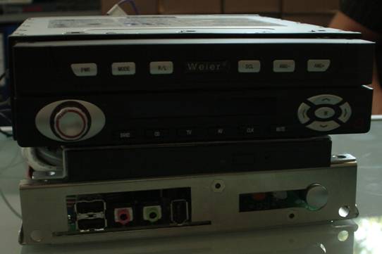
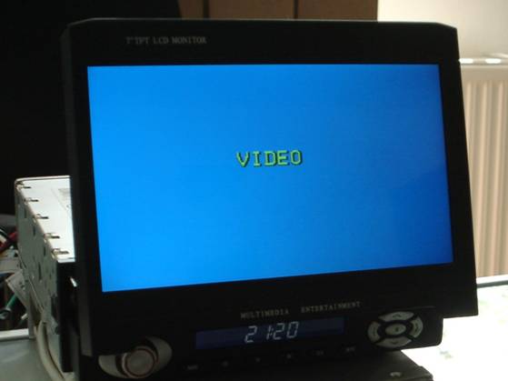
Carputer is nothing but the combination of CAR and COMPUTER; it has acquired the name since a computer is sitting inside a car dashboard. The device is very small and slim such that it can be easily seated in the slot available in car dashboard. The Carputer whole setup is shown in Figure 2 below. It has two units includes a computer unit and a 7 inch LCD display. The 7 inch display screen slides out when the system is switched ON. The below unit has the main board and all computer hardware�s that were inherited from Mini PC and Laptop technology. The monitor unit has provisions to connect antenna for the purpose of TV and Radio. Both the units have its separate remote controls. The Power supply of the whole system is connected to the car battery via 12V AC converter. The Infra red receiver shown in below figure is connected to a 9 pin serial port in the computer unit or via an USB adapter. It has a small credit card size remote control which is very easy to handle the software. The remote control acts as a remote mouse. Each and every accessories of the product will be briefly discussed in further sections.
The Front view of the whole setup when the system is not functioning is shown in Figure 3.
Figure 3: Carputer Setup Front view
Figure 4: Power Supply (12V AC Converter) The Display unit is a 7 inch LCD screen slides outside when the system is switched ON. It has its own integrated TV and Radio circuit which can be used with the help of an antenna. The PC output can also be connected to the display unit via TV out cable. Depends on the requirements, the customer can switch from PC operations to Radio or TV with the help of its respective remote control. Below Figure 5 shows the full view of the display unit. The display unit can also be connected to a CD changer for Music entertainment. It has various switches to change the CD�s from the CD changer also possible to change CDs from remote control. The small LCD display below the screen on the front panel shows the information about the radio frequency, TV channel information, Timer, CD and Track numbers. It has separate buttons for mute control, volume control, and a knob to search frequency for radio and TV. Backside of the unit has provisions to connect antenna, and to receive output from the computer.
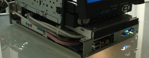
Figure 5: �7 inch� LCD Display Unit The below figure 6 shows the PC Unit. It contains the main motherboard chipset with 256MB DDR RAM and 40 GB laptop hard disk. The processor can be varied depends on the customers requirements. The PC has no keyboard or mouse connected; the whole PC operations can be done via PC-DVD Creative Infra PC remote control will be discussed in detail later.
Figure 6: PC Unit The power supply of the computer is 12 V taken from the CAR battery and connected via an AC adapter. Various display units on the back seat and various game controls are also possible via USB ports available. The PC display has been brought to the LCD screen via TV out cable.
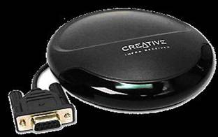
This credit card sized remote control by Creative Labs is one of the most versatile remote controls that you can acquire for your PC. With this remote control, you can not only control a wide array of software programs, but also other popular multimedia player programs such as Microsoft Media Player and Winamp. This remote control can also act as a remote mouse! Installation and setup is simple, it simply plugs into any available standard 9-pin serial port or via USB adapter. This remote control includes Remote Selector software, which not only enables you to be able to use this remote control with a wide array of programs, but it also works with all versions of Microsoft Windows! Due to its huge advantage the mouse and keyboard of the PC has been replaced by this Creative Infra remote Control [1]. It is shown in the Figure 7.
Figure 7: Creative Infra PC-DVD Remote Control
The general features includes, � Credit card size multimedia remote control � Acts as a remote mouse � Great Windows compatibility � Receiver unit plugs into standard 9-pin serial port also via USB adapter. It is compatible with all the below mentioned software with the help of its decoder card, � ATI MultiMedia Center � Chromatic Research Mpact2 � CineMaster Software Engine � CoolDVD � Creative Encore Dxr2 � Creative Encore Dxr3 � Creative PlayCenter � Creative PlayCenter 2 � LuxSonor LS-220 (Creative Labs CT7160 Inlay Decoder Card) � Microsoft Media Player � Microsoft Media Player 7 � PowerDVD (may not work with PowerDVD XP) � RealMagic Hollywood + � RealMagic XCard � WinAmp 2.x (May not work with WinAmp 3) � WinDVD The below figure 8 shows the Creative Infra PC-DVD remote control receiving unit. The Infra receiver has a 9-pin serial port should be connected to COM1 or COM4 port. It is also compatible with USB-SERIAL port adapter.
Figure 8: Infra PC-DVD Remote Receiver Unit. The receiving unit�s requirements are � 9-pin serial port (COM1-COM4) or USB-Serial Adapter. � Windows 95/98/ME/NT4/2000/XP � Supported multimedia decoder or software � CD-ROM drive for driver and software installation
The main goal of the Carputer project is to implement GPS Navigation, DVD, Music and Video Player in Car. Comparatively with the present GPS Navigation available in the market, the Carputer is cost effective with all the media entertainment system with its own software controlled by a remote control. Surfing Internet is also possible with a wireless LAN wherever hot spot is available. Customer can avail various above said media entertainment along with TV and RADIO with a separate remote control for an affordable price.
The evolution of small mini PC has started earlier itself. Many companies and research scholars involved in similar kind of project more then 2 years. However, no one has come to an end without problems. Most of the companies are facing problems with the input devices and recommending standard input device like mouse and keyboard for Carputer, which is not an ideal solution to operate while driving a car. On the other hand they are facing problems while integrating the Carputer in to the car dashboard since each and every company designing their own PC unit hardware.
Xenarc Technologies a leading LCD Monitor manufacturing company in USA currently involved in the project called �Mini P3 Aluminum Car PC�.
Figure 9: �7 inch LCD Touch Screen. The company used �7 inch LCD touch screen� for the project in order to replace the standard input devices like mouse and keyboard shown in Figure 9. However the touch screen option is not so good enough to operate while driving a car also to select small menus since the screen is only 7 inches. Also LCD screen freezes in abnormal cold weather condition. The below Figure 10 shows the view of the Mini P3 Aluminium Car PC [2].
4.2.1 Mini P3 Aluminium Car PC Vehicle Personal Computer opens up the world of in-vehicle entertainment. Couple this multimedia PC with the portable high-resolution VGA monitors and other computer peripherals, makes the system capable for GPS Navigation, MP3 playback, in-car theatre, in-car gaming, and in-car office. This offers superior 2D/3D graphic performance and Soft DVD MPEG-2 playback with hardware motion compensation which allows its user to experience life like audio and video. Use this unit as a music and movie jukebox by downloading songs and movies into its built-in hard drive is possible. Since this is an open-architecture, customer can use their creativity to create customized in-car entertainment system. Compact and light - with a footprint of 5.75" x 9.84" x 1.65" and weighing in at 2 lbs, this mini Pentium 3 based computer system has aluminium casing and takes 12V DC, making it perfect for in-vehicle computing use. Customers can install their choice of a CD-ROM, DVD-ROM, CD-RW, or DVD-ROM/CD-RW combo drive. The draw back of this specified product is there is no input devices mentioned along with the product [2].
Figure 10: Mini P3 Aluminium Car PC
Figure 11: Mini P3 Aluminium Car PC
The updated version of the above mentioned product is �XENARC
CP-1000�
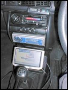
4.3 Peter Bridger a one man company Peter Bridger has a one man company in United Kingdom involved in the Carputer project for about more than 2 years. He experienced so many problems while implementing a computer in a CAR. His experience gives motivation to think on various sides to overcome the problems in the master thesis. His first try to keep the mother board of the computer in the dash board case as shown in Figure 12. The monitor was placed near the gearbox just below the music system provided by the car manufacturer. The setup is shown in Figure 12. A full view of the LCD monitor located near the gearbox is shown below in Figure 14 [3].
Figure 12: Motherboard in dashboard case.
Figure
Figure 14: Full view of the LCD monitor located near the gearbox
One of the main uses of Carputer is for GPS Navigation route planning. He made a little round up of his experiences with different route planning software. He got a GPS receiver along with software Route 66 shown in Figure 13. It is an average piece of software that talks to the GPS unit and can plan routes from the maps available. Info Map is a powerful software shown in Figure 15 can able to update the map with the GPS data every second and even leaves a little trail of where you have been. As for route planning it is pretty good. AutoRoute is Microsoft product shown in Figure 17 offering a very easy use and a very good all rounder for GPS Navigation. For gaining information about near by landmarks, cash points and other such places of interests this software plays a vital role to the best of customer�s satisfaction [3].
Figure 15: GPS software Route 66.
Figure 16 : GPS software Infomap
Figure 17: GPS software Auto Route. Fixing a computer into a car is not a daily procedure; he didn't have any instructions to follow or beaten path to take when working on the project. This meant in reflection, some choices he made were not the best, while others worked out ok. This sections deal the positive and negative sides of the project [3].
Carputer Display Computer monitors are not cheap and are the most expensive part of any computer system. Trying to find a small and cheap display for this project wasn't easy, and was one of the biggest sticking points in the early days. He finally found a good priced monitor at Merconnet, which was quite big at 5.6" compared to others he found it was fairly reasonably priced. Admittedly it is not perfect, but for the price he needs to do with it. Mostly the LCD touch screen monitors are bit expensive.
Voice Command Programming his own voice command software in Visual Basic was pretty straight forward and enabled his product to play any song at will. Without diverting the drivers attention from the road is an added advantage and he planned to improve the software for the next version.
GPS One of the things that he wanted from the start, but only came together towards the end is the GPS Navigation system. Finally he could watch the map zoom into his current position, and the navigation map software works perfectly updating every second.
DVD Playback He did not have major worries about the DVD playback process with 800MHz Pentium 3 processor. He picked up a cheap DVD drive which came with a copy of Power DVD that solves the DVD Playback worries.
Keyboard / Mouse Interface Both the standard input device mouse and keyboard are very small but very functional, perfect for the task in hand. The keyboard was a bit pricey, but it is a solid piece of kit. The mouse was also very usable and durable.
Size of Components The whole idea really started after seeing the size of the mini-ITX Eden motherboard and he had been lucky enough to find a whole host of other components that have compromised the project to be very small.
Windows 2000 Operating System His main home computer is an Athlon 2000 XP + powered rig, nice and up to date, but he was using W2K on it rather than XP. Because he felt 2K is slicker and cleaner. When he first tested the Carputer's Eden motherboard with 64MB stick of RAM in it. Windows 2000 ran perfectly on it, starting up very fast. However when he upgraded it to Windows XP, it slowed to a snails pace. The Windows 2000 installation had been stripped down all non essential services so that the system starts very quickly. It was very stable and runs whatever great stuff software he installed on it.
What Went Wrong A big project like this could not have been a smooth ride and of course it was not. Things did not always turn out as he thought they would. So what exactly went wrong?
No Touch Screen One of the ways he hoped to keep this vision was by having a touch screen interface, so that it will replace the standard input devices like mouse and keyboard. Sadly touch-screen devices are expensive and causes unusual problem in cold weather conditions. Finally he found such a device, a 7" SVGA touch screen monitor for about $499 price which was not certainly cheap.
Monitor Size and Quality The LCD small screen showed a good look appearance because of its 5.6" monitor size however it is very small and not flexible for the customer�s usage. Also it was not very clear since it takes a TV video signal rather than a standard VGA monitor signal. By using large icons and font plus some high contrast colours the situation can be improved. Although at the end of the day, many applications can be a real strain to read and use. By using custom designed interfaces the problems can be rectified.
Power Efficiency The Carputer takes the 12DC from the car battery, uses an inverter to transform this into 240AC which then makes its way into the Carputers PSU that then transforms this into the 12DC, 5DC, etc... With respect to the computer needs. Now the project concentrates to use the power directly without power loss.
Only a Few Voice Commands Voice recognition is very useful and powerful, however it is only written to playback music. He would like to extend the system in the next version so that he can control every part of the Carputer with voice, so the customer never needs to take eyes off from the road.
What Could Be Improved? The above sections described the good and the bad, now what can be improved on and used in Carputer version 2?
Larger and Clearer Screen Much of what the Carputer offers is visual, from GPS maps to DVD films. So for this reason a good monitor is a must, whether this will be achieved from merely using a large 7"/10" screen or a monitor using a VGA input, has to be considered to concentrate the key things to improve the next version of the project.
Better Performance Surely the C3 processor will never compete with a P4 chip, but considering every drop of power he was always eager to make more power, more performance of the system. Even though the system has Quake3, Elite Force and the Sims running on the Carputer, he was interested always for further enhancements. The new range of mini-ITX boards from VIA look great, with a 933MHz C3 chip, enhanced graphics and hardware assisted DVD decoding. Probably the next version will be released with the above mentioned configuration.
Wireless LAN Currently software can be loaded onto the Carputer like normal PC operations just by popping a CD or DVD. For better data transfer a wireless LAN would be an ideal solution, it needs two USB wireless modules and things would be made much easier.
Auto Starting The next enhancement of the Carputer is to start the system automatically during car start-up. No more burdens to turn it on, it'll always be there, ready for GPS, games, DVD or anything the customer needs.
FM Sound Transmitter In the current system, the soundcard of the Carputer goes through a CD-Tape adapter into the cars stereo system, not exactly comparable to an optical audio connection. So in version 2 the system will be using a mini FM radio transmitter, so the customer can just tune the car radio into the Carputers broadcast.
Enhanced GPS As it stands the GPS does a great job, but it could do better? The system should plan a route and should instruct the customer when to turn left, right or whatever. The customer should put total faith in the GPS system to tell exactly where to go, just by talking.
Lot of companies and research scholars from UK, USA and Canada are deeply involved in the same project for more than years, however with the input device each company facing different problems by implementing standard or customized input devices, also facing problems to fix it in car dash board.
A software development process is a process used to develop computer software, which refers to one or more computer programs and data held in the storage of a computer for some purpose. Software program performs the function of the program it implements, either by directly providing instructions to the computer hardware or by serving as input to another piece of software. Data software exists solely for its eventual use by other program software. It may be an ad hoc process, devised by the team for one project but the term often refers to a standardised, documented methodology which has been used before on similar projects or one which is used habitually within an organisation [20].
Software Engineering is the profession concerned with creating and maintaining software applications by applying computer science, project management and other technologies and practices. Software Engineering applications are used in wide range of activities, from industry to entertainment. Software applications improve user productivity and quality of life. Application software examples are office suites, video games, and the World Wide Web. System software examples are embedded systems and operating systems. In 1967, a NATO study group coined the phrase "software engineering" as a response to their belief that the current software crisis could be solved by adapting existing engineering practices to software development. This crisis was characterized by the consistent development of low quality software which exceeded cost limits and development deadlines. Twenty years later, the software crisis was still thriving. Consider the following analysis done by the Government Accounting Office (GAO) in 1979 on the state of management information systems software development [20].
Out of the 163 contractors and 113 government personnel surveyed, � 60% of their contracts had schedule overruns, � 50% of their contracts had cost overruns, � 45% of the software could not be used, � 29% of the software was never delivered, and � 19% of the software had to be reworked to be used. Even today the software crisis is a significant problem that software engineering must address. Dr. John Dalbey of California Polytechnic State University organized the following information about the current state of the software crisis.
5.2.2 Software Chronic Crisis Recognition In the September 1994 issue of Scientific American, W. Wayt Gibbs chronicled the following example of the modern software crisis in his article "Software's Chronic Crisis". "Denver's new international airport was to be the pride of the Rockies, a wonder of modern engineering. Twice the size of Manhattan, 10 times the breadth of Heathrow, the airport is big enough to land three jets simultaneously in bad weather. Even more impressive than its girth is the airport's subterranean baggage-handling system. Tearing like intelligent coal-mine cars along 21 miles of steel track, 4,000 independent "telecars" route and deliver luggage between the counters, gates and claim areas of 20 different airlines. A central nervous system of some 100 computers networked to one another and to 5,000 electric eyes, 400 radio receivers and 56 bar-code scanners orchestrates the safe and timely arrival of every valise and ski bag. At least that is the plan. For nine months, this Gulliver has been held captive by Lilliputians-errors in the software that controls its automated baggage system. Scheduled for takeoff by last Halloween, the airport's grand opening was postponed until December to allow BAE Automated Systems time to flush the gremlins out of its $193-million system. December yielded to March. March slipped to May. In June the airport's planners, their bond rating demoted to junk and their budget haemorrhaging red ink at the rate of $1.1 million a day in interest and operating costs, conceded that they could not predict when the baggage system would stabilize enough for the airport to open� [21]. Eventually the Denver International Airport (DIA) did open, but the advanced baggage system was only partially functioning. The four delayed openings of the airport caused many residents to speculate that DIA really stood for "Do It Again," "Doesn't Include Airlines," or "Done In April". In order to finally open the terminal, the city invested $51 million to install a conventional baggage system as a work around to the high-tech system. Ironically, the conventional system was completed four weeks ahead of schedule and $3.4 million under budget [21 & 23]. The obvious question is: why was the high-tech system so difficult to implement? According to Fred Brooks a scientific software analyst, part of the answer to this question is that software is inherently complex. Unlike other engineering disciplines, software systems lack repeated elements. While a building may be constructed of thousands of bricks, a software product will combine pieces with the same functionality into a single subroutine. This means that software is composed of thousands of unique parts rather than repeated parts. Software systems also have very large numbers of operational states which makes exhaustive testing impossible. A bridge, on the other hand, is also a large and complex structure, but only a handful of extreme states (i.e. inclement weather, heavy traffic, earthquakes) need to be tested to insure the reliability of the bridge. In addition to inherent complexity, Brooks also mentions some other essential qualities of software such as changeability and invisibility that contribute to the software crisis. Changeability refers to the fact that all software eventually gets changed. Clients may want to add new functionality or developers may want to port the program to a new hardware platform. While it is unthinkable that a civil engineer would be asked to move a bridge to a new location, software engineers are regularly expected to perform major modifications on existing software. Invisibility refers to the fact that software is not a physical entity. Because of this, it is difficult for the human mind to use some of its most powerful conceptual tools in the development of software. With these difficulties in mind, the need for effective software engineering becomes even more urgent. Software systems are playing an increasingly common role in our everyday lives. Failure to develop reliable software systems can cost more than just money and time. Consider the following examples cited by Michael Lyu in the introduction to the Handbook of Software Reliability Engineering: "Unfortunately, software can also kill people. The massive Therac-25 radiation therapy machine had enjoyed a perfect safety record until software errors in its sophisticated control systems malfunctioned and claimed several patients' lives in 1985 and 1986. On October 26, 1992, the Computer Aided Dispatch system of the London Ambulance Service broke down right after its installation, paralyzing the capability of the world's largest ambulance service to handle 5000 daily requests in carrying patients in emergency situations. In the recent aviation industry, although the real causes for several airliner crashes in the past few years remained mysteries, experts pointed out that software control could be the chief suspect in some of these incidences due to its inappropriate response to the pilots' desperate inquires during abnormal flight conditions" In further sections, we will examine some of the fundamental concepts of software engineering such as processes and meta processes, life cycle of software development, two major paradigms of developing software and Software Quality Characteristics [21].
A project is a temporary endeavour undertaken to create a unique product or service. Temporary means that the project has an end date. Unique means that the project�s end result is different than the results of other functions of the organization. It can also comprise an ambitious plan to define and constrain a future by limiting it to set goals and parameters. The planning, execution and monitoring of major projects sometimes involves setting up a special temporary organization, consisting of a project team and one or more work teams. A project usually needs resources.
In software engineering, a project lifecycle models how a project is planned, controlled and monitored from its inception to its completion. In the earliest stages and in the last stages of the project lifecycle, Software architecture, requirements and system definition is an issue: � What is the market for the system/software and its competition? � What is the platform of the system/software? � How much time is available to the project? � How many skill-sets are needed? Over the years, a number of different models have been developed, beginning with the oldest and simplest being the "Waterfall Model� [21]. However, as software has become larger and more complex, this method of development has been found to be counter productive, especially when large teams are involved. Models that are iterative have evolved including Prototyping, Evolutionary Prototyping, Incremental Development, spiral model, V modal, and Chaos model. The use of these models for the most part confined to the overall management of the project. However projects are now considered better controlled if the model best suited to the individual aspects of the project. For example, a project may be managed using the Incremental Development model, but during each increment the Documentation is created managed using the Waterfall Model and the Code development managed using the 'V' model. The level of formality and complexity of the lifecycle for each project is constrained by any number of factors, including budgetary constraints, experience, size and complexity of the project and development team. Some experienced and highly respected project leaders and programmers consider rigid application of lifecycle plans to be a theory that does not work well in practice, the very highly regarded project leader of the Linux kernel made the following statement on the Linux kernel mailing list: �No major software project that has been successful in a general marketplace has ever gone through those nice lifecycles�. ISO 12207 is a standard that was developed to describe the method of selecting, implementing and monitoring a lifecycle for a project.
In software engineering and project management, the term methodology is a codified set of recommended practices, sometimes accompanied by training materials, formal educational programs, worksheets and diagramming tools. Software engineering methods span many disciplines, including project management, analysis, specification, design, coding, testing, and quality assurance. All of the methods guiding this field are collations of all these disciplines [21].
An organization is a formal group of people with one or more shared goals. This topic is a broad one. According to management science, most human organizations fall roughly into five types:- � Pyramids or hierarchies � Committees or juries � Matrix organisations � Ecologies � Composite organisations Some managers, who are held accountable for software development, may seek to find the commonalities in the efforts of their organizations. If those managers are process-oriented, rather than people-oriented, task-oriented, profit-oriented, project-oriented, etc. Then they may seek methodologies or other proxies which can serve as templates for the software development process. Of course, it is entirely rational for other managers who are not process-oriented to use a documented software development process or methodology. In such a case one might say that the methodology is used by them as a "proxy" for the necessary set of process-oriented skills required in any software engineering project [21].
5.3 Processes and meta-processes A growing body of software development organisations implement process methodologies. Many of them are in the defence industry, which in the U.S. requires a �Rating� based on 'Process models' to obtain contracts [21]. Rating is a means of classifying things in different categories. Some of them are:- � ELO rating system � Suitability-to-audience ratings � Motion picture rating systems � MPAA film rating system � Film rating systems � TV Parental Guidelines � V � chip ratings � Entertainment Software Rating Board � Fuel performance ratings � Octane rating � Cetane rating � PR raring � Nielsen Ratings � Naval rating
5.3.1 Capability Maturity Model The Capability Maturity Model (CMM) grades organizations on how well they create software according to how they define and execute their processes. The Capability Maturity Model of the Software Engineering Institute at Carnegie Mellon University describes the maturity of software development organisations on a scale of 1 to 5. It has been used extensively for avionics software and for government projects since it was created in the mid 1980�s. The Software Engineering Institute has subsequently released a revised version known as the Capability Maturity Model Integration (CMMI) [21].
ISO 9000 describes standards for formally organizing processes with documentation. It specifies requirements for a Quality Management System overseeing the production of a product or service. It is not a standard for ensuring a product or service is of quality; rather, it attests to the process of production, and how it will be managed and reviewed. It was originally created by the British Standard Institute as BS 5750. The standard is now maintained by ISO (the International Organization for Standardization) and administered by accreditation and certification bodies [21].
ISO 15504 is a �framework for the assessment of software processes� developed by the International Organization for Standardization (ISO). It is also known as SPICE (Software Process Improvement and Capability dEtermination). The software process life cycle is also gaining wide usage. This standard is aimed at setting out a clear model for process comparison. SPICE is used much like CMM and CMMI. It models processes to manage, control, guide and monitor software development. This model is then used to measure what a development organization or project team actually does during software development. This information is analyzed to identify weaknesses and drive improvement. It also identifies strengths that can be continued or integrated into common practice for that organization or team [21].
Six Sigma is a quality management program to achieve �six sigma� levels of quality. It was pioneered by Motorola in the mid � 1980s and has spread to many other manufacturing companies. It continues to spread to service companies as well. In 2000, Fort Wayne, Indiana became the first city to implement the program in a city government. It aims to have the total number of failures in quality, or customer satisfaction, occur beyond the sixth sigma of likelihood in a normal distribution of customers. Here sigma stands for a step of one standard deviation; designing processes with tolerances of at least six standard deviations will, on reasonable assumptions, yield fewer than 3.4 defects in one million. Generally, it is a project management methodology that uses data and statistical analysis to measure and improve a company's operational performance. It works by identifying and eliminating "defects" in manufacturing and service-related processes. The maximum permissible defects are 3.4 per million opportunities. However Six Sigma is manufacturing-oriented, not software development-oriented and needs further researches to even apply to software development [21].
Defects here refer to: - In Software Engineering, the non � conformance of software to its requirements, often but incorrectly, called bug.
5.3.5 Agile software development In Software Engineering, agile software development or agile methods refers to low-overhead methodologies that accept that software is difficult to control. They minimize risk by ensuring that software engineers focus on smaller units of work. One way in which agile software development is generally distinguished from �heavier� more process-centric methodologies, for example the waterfall model, is by its emphasis on values and principles, rather than on processes. Agile Software methodologies such as �Extreme Programming� and �Lean Software Development� are full blown methods that take an incremental or evolutionary approach to software development [21].
Extreme Programming: It is a method in or approach to software engineering, formulated by Kent Beck, Ward Cunningham, and Ron Jeffries. Kent Beck wrote the first book on the topic, Extreme Programming Explained, published in 1999. It is the most popular of several agile software development methodologies. The generalisation of extreme programming to other types of projects is extreme project management [21].
Lean Software Development: Lean Manufacturing is a business initiative to reduce waste in manufactured products. The basic idea is to reduce the cost systematically, throughout the product and production process, by means of a series of engineering reviews. The crucial insight is that most costs are assigned when a product is designed. Often an engineer will specify familiar, safe materials and processes rather than inexpensive, efficient ones [21]. This reduces project risk, that is, the cost to the engineer, while increasing financial risks, and decreasing profits. Good organizations develop and review checklists to review product designs.
A common mistake people make concerning software is assuming that the majority of software development is programming. When they think of programming, their minds conjure up the image of a late-night hacker pounding out code on an old computer in the basement of a musty apartment. While this is certainly one approach to programming, it is hardly the norm and definitely not the way the majority of current software is developed. In fact, programming is only a fraction of the software development process. Today, many other steps are involved in the successful development and deployment of computer software. Taken together, all these steps are referred to as the software lifecycle. Often these steps are described by models called software life cycle models. In the next two sections we will examine two of these models: the waterfall model and the spiral model. First, however, we need to describe the basic processes that make up the software lifecycle [20 & 21]. Most models of the software lifecycle include the following six processes: requirements engineering, design, programming, integration, delivery, and maintenance. The list below gives a description of each process.
5.4.1 Requirements Engineering During this process, developers and clients meet to discuss ideas for the new software product. Developers use a variety of techniques in order to assess the real needs of the client. One such technique is rapid prototyping in which a prototype program is built that can mimic the functionality of the desired software. Using this prototype, clients can better understand how the final product will behave and can determine whether this behaviour is what they really need. Unless the requirements engineering process is done properly, the resulting software will not be useful to the client even though it may run correctly. The requirements engineering process is completed when the specifications for the new software product are written in a formal document called the �requirements specification document� [21].
During this process, the developers decide how they will construct the software so that it meets the specifications agreed upon in the requirements specification document. Usually the design of the software goes through several stages in which it becomes progressively more detailed. This approach to design is called stepwise refinement, and it allows the developers to manage the complexity of software by postponing decisions about details as late as possible in order to concentrate on other important design issues. When the design is complete, it is recorded in the �design specification document� [21].
During this process, teams of programmers write the actual code of the software. The software is divided into separate units called modules in order to handle the complexity of the programming process. Not only are these teams responsible for coding their modules, they are also responsible for proper documentation describing their code and for testing the code to insure correctness [21].
During this process, the individual modules of the software product are combined to form the integrated software product. Since the modules were developed separately, testing is crucial to the integration process. Even with a good design, incompatibilities between modules are likely to exist. These problems need to be identified and corrected to complete the integration [21].
During this process, the developers deliver the completed software to the clients. Usually the clients will conduct acceptance testing on the software to determine whether or not it meets the specifications agreed upon in the requirements specification document. Once the software is accepted, it is installed and used by the client [21].
During this process, the software undergoes various changes after delivery in order to fix bugs, add new functionality, port the software to new platforms, or adapt the software to new technologies. Although it may seem that the software should be finished after delivery, this is far from true [21]. All successful software products evolve over time to meet the changing needs of the clients. You may be surprised to discover that of all these processes, maintenance dominates the cost of the lifecycle. The graph below shows the relative cost of the processes that make up the software lifecycle. Because maintenance costs are so important, many developers are beginning to use design approaches that result in software which is easier to maintain [21 & 22].
Figure 18 : Approximate relative costs of the phases of the software life cycle Many different models have been created to represent the software life cycle. Although these models use various names for the processes of the life cycle, they all include the six processes described above in one way or another. In addition, these models usually emphasize some other aspect of software development such as a particular design technique (e.g., rapid prototyping), management technique (e.g., risk management), or the model describes a limited domain of software development (e.g., real-time software) [20].
5.5 Software Quality Characteristics The goal of software engineering is, of course, to design and develop better software. However, what exactly does "better software" mean? In order to answer this question, this section introduces some common software quality characteristics. Six of the most important quality characteristics are maintainability, correctness, reusability, reliability, portability, and efficiency [22].
Maintainability: Maintainability is "the ease with which changes can be made to satisfy new requirements or to correct deficiencies�. Well designed software should be flexible enough to accommodate future changes that will be needed as new requirements when it comes to light. Since maintenance accounts for nearly 70% cost of the software life cycle, the importance of this quality characteristic cannot be overemphasized. Quite often the programmer responsible for writing a section of code is not the one who must maintain it. For this reason, the quality of the software documentation significantly affects the maintainability of the software product.
Correctness: Correctness is "the degree with which software adheres to its specified requirements". At the start of the software lifecycle, the requirements for the software are determined and formalized in the requirements specification document. Well designed software should meet all the stated requirements. While it might seem obvious that software should be correct, the reality is that this characteristic is one of the hardest to assess. Because of the tremendous complexity of software products, it is impossible to perform exhaustive execution-based testing to insure that no errors will occur when the software is run. Also, it is important to remember that some products of the software lifecycle such as the design specification cannot be "executed" for testing. Instead, these products must be tested with various other techniques such as formal proofs, inspections, and walkthroughs.
Reusability: Reusability is "the ease with which software can be reused in developing other software". By reusing existing software, developers can create more complex software in a shorter amount of time. Reuse is already a common technique employed in other engineering disciplines. For example, when a house is constructed, the trusses which support the roof are typically purchased preassembled. Unless a special design is needed, the architect will not bother to design a new truss for the house. Instead, he or she will simply reuse an existing design that has proven it to be reliable. In much the same way, software can be designed to accommodate reuse in many situations. A simple example of software reuse could be the development of an efficient sorting routine that can be incorporated in many future applications.
Reliability: Reliability is "the frequency and criticality of software failure, where failure is an unacceptable effect or behaviour occurring under permissible operating conditions". The frequency of software failure is measured by the average time between failures. The criticality of software failure is measured by the average time required for repair. Ideally, software engineers want their products to fail as little as possible (i.e., demonstrate high correctness) and be as easy as possible to fix (i.e., demonstrate good maintainability). For some real-time systems such as air traffic control or heart monitors, reliability becomes the most important software quality characteristic. However, it would be difficult to imagine a highly reliable system that did not also demonstrate high correctness and good maintainability.
Portability: Portability is "the ease with which software can be used on computer configurations other than its current one". Porting software to other computer configurations is important for several reasons. First, "good software products can have a life of 15 years or more, whereas hardware is frequently changed at least every 4 or 5 years. Thus good software can be implemented, over its lifetime, on three or more different hardware configurations". Second, porting software to a new computer configuration may be less expensive than developing analogous software from scratch. Third, the sales of "shrink-wrapped software" can be increased because a greater market for the software is available.
Efficiency: Efficiency is "the degree with which software fulfils its purpose without waste of resources". Efficiency is really a multifaceted quality characteristic and must be assessed with respect to a particular resource such as execution time or storage space. One measure of efficiency is the speed of a program's execution. Another measure is the amount of storage space the program requires for execution. Often these two measures are inversely related, that is, increasing the execution efficiency causes a decrease in the space efficiency. This relationship is known as the space-time trade-off. When it is not possible to design a software product with efficiency in every aspect, the most important resources of the software are given priority.
The table below summarizes each of the six quality characteristics. With these characteristics, the answer to the question "What is better software?" becomes much more precise. Using these characteristics, software engineers can assess software products for strengths and weaknesses. The two most prominent software development paradigms are the classical or procedural paradigm and the object oriented paradigm.
Table 1: Software Quality Characteristics
Software Model and Programming Paradigms
Software Model is a necessary thing for successful completion of the software with reduced �bugs�. It provides a structure which makes easier for problem solving while implementation. It experiments to explore multiple solutions for a single piece of problem. It furnishes abstraction to manage the complexity of the software program. It reduces the delivery time to market thereby overcoming business problems [21]. It mainly reduces the development costs and manages the risk of mistakes. Some software development methods are listed below:- � Top-Down and Bottom-up Model � Prototyping Model � Evolutionary Prototyping Model � Iterative and Incremental development Model � Waterfall Model � Spiral Model � Chaos Model Each and every model will be discussed in detail below.
6.1.1 Top � Down and Bottom-up Model: Top-down and Bottom-up are approaches to the software development process, and by extension to other procedures, mostly involving software. In the Top-Down Model an overview of the system is formulated, without going into detail for any part of it. Each part of the system is then refined by designing it in more detail. Each new part may then be refined again, defining it in yet more detail until the entire specification is detailed enough to begin development [21].
The prototyping model is a software development process that begins with requirements collection, followed by prototyping and user evaluation. Often the end users may not be able to provide a complete set of application objectives, detailed input, processing or output requirements in the initial state. After the user evaluation, another prototype will be built based on feedback from users, and again the cycle returns to customer evaluation [21].
6.1.3 Evolutionary Prototyping Model: Code and fix development is not so much a deliberate strategy as an artefact of schedule pressure on software developers. Without much in the way of a design, programmers immediately begin producing code. At some point, testing begins (often late in the development cycle), and the inevitable bugs must then be fixed before the product can be shipped [21].
6.1.4 Iterative and Incremental development: Iterative and Incremental development is a software development process, one of the practices used in Extreme Programming. The basic idea behind iterative enhancement is to develop a software system incrementally, allowing the developer to take advantage of what was being learned during the development of earlier, incremental, deliverable versions of the system. Learning comes from both the development and use of the system, wherever possible. Key steps in the process were to start with a simple implementation of a subset of the software requirements and iteratively enhance the evolving sequence of versions until the full system is implemented. In each iteration, design modifications are made along with addition of new functional capabilities [21].
The Waterfall model is a software development model first proposed in 1970 by W.W.Royce, in which development is seen as flowing steadily through the phases of requirements analysis, design, implementation, testing (validation), integration, and maintenance [21]. In the original article, Royce advocated using the model repeatedly, in an iterative way. However, most people do not know that some have discredited for use as a Real World process. In practice, the process rarely proceeds in a purely linear fashion. Iterations, by going back to or adapting results of the precedent state, are common.
Figure 19: Waterfall Model The below table shows the explanation about each stages in water fall model.
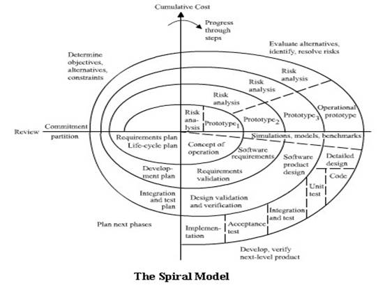
The spiral model is a software development model combining elements of both design and prototyping-in-stages, so it�s a healthy mix of top-down and bottom-up concepts. The spiral model was defined by Barry Boehm. This model was not the first model to discuss iteration, but it was the first model to explain why the iteration matters. As originally envisioned, the iterations were typically 6 months to 2 years long. This persisted until around 2000. However, this model "does not work well for many classes of software, particularly interactive end-user applications." Specifying the requirements for such applications is notoriously difficult since interface design is highly subjective and clients rarely ever understand the real needs the software should meet. As a result, "document-driven standards have pushed many projects to write elaborate specifications of poorly understood user interfaces and decision-support functions, followed by the design and development of large quantities of unusable code". The problem is that a contract is signed before the real requirements of the system are properly understood [22].
Figure 20 : Spiral Model
In computing, the Chaos model is a structure of software development that extends the spiral model and waterfall model. The chaos model was defined by L.B.S. Raccoon. The chaos model notes that the phases of the lifecycle apply to all levels of projects, from the whole project to individual lines of code [21]. � The whole project must be defined, implemented and integrated. � Systems must be defined, implemented and integrated. � Modules must be defined, implemented and integrated. � Functions must be defined, implemented and integrated. � Lines of code are defined, implemented and integrated.
6.2 Aspects of programming paradigms The term "programming paradigm" is extremely fuzzy because it is often used to capture a set of different software-related aspects under a particular catch-phrase. These different aspects are often located on different levels of abstraction and their interrelationships are seldom explicitly formulated. Here a triangle is shown in the following figure to describe the different levels of abstraction that is the view made up a programming paradigm. The form of a triangle express the fact that the number of concepts on a particular level of abstraction increases on higher levels. Furthermore, a layered approach is quite common in computer science theories to clearly separate the concepts on different levels of abstraction. The main advantage of a layered approach is that no knowledge of lower levels is necessary to understand and to work with higher level concepts because ideally, each level of abstraction represents a conceptually closed framework. In reality, unfortunately, the higher level theories are not only much more complex then lower level ones, but they are often incomplete. Therefore, it often becomes necessary to combine several higher level theories to obtain a full coverage of the intended part of the world that should be modelled.
Figure 21 : Aspects of Programming Paradigm Furthermore, that the distinctions between the different levels are not too sharp. Because, �Most programming models are assumed to be essentially equal in their computational power� (Church's thesis), any programming model can be implemented in terms of any other mode [21]l. Thus, it is possible to write object-oriented software in a purely imperative programming language or to implement a deductive database in an object-oriented framework. In the following sections, a break-down of concepts are shown that clearly separates intra-model aspects and that allows for an inter-model comparison of these concepts. Some concepts can be shifted along the abstraction hierarchy, but the current assignment to a particular level is adequate.
6.2.1 HardwareThe first level of abstraction encapsulates the architecture that is implemented in the computer hardware. Today, most computers still have the von Neumann architecture that was introduced in the late 1940s. The architecture consists of a processor that is subdivided into units for computation and control and a memory store that holds the instructions and the data of the program [21]. This architecture is still common in modern computers although it has been greatly optimized by using techniques such as pipelining, caching or parallelism to speed up computation. A recent trend in the hardware community is to turn away from integrated, large-scale systems and towards networks of normal personal computers that jointly work on a computationally demanding task. These virtual supercomputers combine the advantage of lower costs through the use of standard hardware with an extreme scalability that allows to add more computational resources whenever this is necessary.
6.2.2 TheoriesOn the next higher level of abstraction, however, things are different. Theories are conceptualizations of a particular computational model that abstracts away from the characteristics of the hardware. The first theories were aimed at capturing the in-principle capability of a computational device in order to allow for general statements about what can be automatically computed and what cannot. Turing's theory, for example, is a radical mathematical conceptualization of the von Neuman architecture that enables us to formally analyze all possible programs that can be executed on such architecture. Other computational theories are intended as tools to help the programmer to express the ideas of what a program is supposed to do more naturally.
6.2.3 Runtime SystemThe runtime system of a particular programming paradigm provides the environment for the program interpretation and these environments can be radically different. In the more simple forms, they are restricted to administrative tasks such as managing the heap or they provide slightly more elaborate services such as garbage collection. However, there also exist very complex runtime environment that provide complete reasoning engines for logic programming that are for example used in declarative programming languages such as Prolog. Objects and agents and the various relationships that exist between them within their respective programming model are conceptual abstractions that require an implementation such that they can be used by higher levels of abstraction [21].
6.2.4 Programming LanguageIn this level of abstraction, the syntactical framework for the manipulation of the entities on the runtime level is defined. The programs that are written in a particular programming language are either directly interpreted by the runtime system or they are compiled into an intermediate format that is understood by the runtime system or directly to assembler code. The syntactical constructs that are provided by the programming language should allow the programmer to use the underlying semantic concepts efficiently and to express the intended functionality of the program elegantly. For example, it is generally possible to implement a particular conceptual model with any general purpose language, e.g. it is possible to write object-oriented programs in C, but in general, it is much easier and more comfortable for the programmer if the terms of the conceptual framework can be used directly. Even an integration of several conceptual models into a single high level programming language can be problematic as is often difficult to find a good combination of concepts that is not overwhelming for the average user and then to find a concise syntactical representation for these different concepts [21]. 6.2.5 Design LanguageDesign languages are further abstractions from a particular programming language that aim at the conceptual modelling of a system at a more coarse grained level. Design languages often use graphical notations that make it easier from the designer to access the overall system structure. Probably the currently best known design language is the Unified Modelling Language (UML) that tries to integrate several, until then separated design notations under a common hat. Due to the general nature of the core UML, it is not always suited for all problem areas, and therefore, extensions that cover special aspect have already been proposed [21 & 22]. In a more general sense, however, design languages should not necessarily be constraint to modelling aspects of the system. The reason for this view is that these frameworks provide their own set of structural abstractions that represent a "language" on this particular level of abstraction.
6.3 Types of programming paradigms Various available programming paradigms are listed below � Procedural Programming � Structured Programming � Imperative Programming � Declarative Programming � Functional Programming � Literate Programming � Object Oriented Programming � Concurrent Programming � Component Oriented Programming Each sections are discussed below [21].
Procedural Programming is a method of computer programming based upon the concept of the unit and scope. A procedural program is composed of one or more units or modules � either user coded or provided in a code library. Each module is composed of one or more procedures, also called a function, routine, subroutine, or method depending on programming language. It is possible for a procedural program to have multiple levels or scopes, with procedures defined inside other procedures. Each scope can contain variables which cannot be seen in outer scopes.
Structured Programming can be seen as a subset or sub discipline of procedural programming, which is one of the major programming paradigms. It is most famous for removing or reducing reliance on the GOTO statement. Historically, several different structuring techniques or methodologies have been developed for writing structured programs. The two most common are Jackson Structured Programming which is based on aligning data structures with program structures and Dijkstra�s structured programming, which is based on splitting programs in to sub-sections, each with a single point of entry and of exit.
In computer science, imperative programming, as opposed to declarative programming, is a programming paradigm that describes computation in terms of a program state and statements that change the program state. In much the same way as the imperative mood in natural languages expresses commands to take action; imperative programs are a sequence of commands for the computer to perform. The hardware implementation of almost all computers is imperative; nearly all computer hardware is designed to execute machine code, which is native to the computer, written in the imperative style. From this low-level perspective, the program state is defined by the contents of memory, and the statements are instructions in the native machine language of the computer.
6.3.4 Declarative programming: Declarative Programming is an approach to computer programming that takes a different approach from traditional imperative programming in Fortran, C++ or Java. Whereas imperative programming gives the computer a list of instructions to execute in a particular order, declarative programming describes to the computer a set of conditions and lets the computer figure out how to satisfy them. Declarative programming includes both functional programming and logic programming.
Functional programming is a programming paradigm that treats computation as the evaluation of mathematical functions. In contrast to imperative programming, functional programming emphasizes the evaluation of functional expressions, rather than execution of commands. The expressions in these languages are formed by using functions to combine basic values.
Literate programming is a certain way of writing computer programs. It is seen as communications to human beings, as works of literature, hence the name �literate programming�.
6.3.7 Object oriented programming: Object �oriented programming (OOP) is a computer programming paradigm that emphasizes the following aspects: � Objects � packaging data and functionality together into units within a running computer program; objects are the basis of modularity and structure in an object � oriented computer program. � Abstraction � The ability for a program to ignore some aspects of the information it�s manipulating, i.e the ability to focus on the essential. Each object in the system serves as a model of an abstract �actor� that can perform work, report on and change its state, and �communicate� with other objects in the system, without revealing how these features are implemented. Processes, functions or methods may also be so abstracted, and when they are, a variety of techniques are required to extend an abstraction: � Encapsulation � Also called information hiding: Ensures that objects cannot change the internal state of other objects in unexpected ways; only the object�s own internal methods are allowed to access its state. Each type of object exposes an interface to other objects that specifies how other objects may interact with it. This prevents users from breaking the invariants of the program. � Polymorphism � References to and collections of objects may refer to objects of different types, and invoking an operation on a reference will produce behaviour depending on the actual type of the referent. � Inheritance � Organizes and facilitates polymorphism and encapsulation by permitting objects to be defined and created that are specialized types of already-existing objects-these can share (and extend) their behaviour without having to re implement that behaviour. This is typically done by grouping objects into classes, and defining classes as extensions of existing classes, thus and grouping classes into trees or lattices reflecting behavioural commonality. It is in fact a set of ideas which mostly existed before. They have been brought together, with associated terminology, to create a programming framework. Together the ideas behind OO are said to be so powerful they create a Paradigm shift in programming. The exact definitions of these have some variation depending on point of view.
Parallel programming (also concurrent programming), is a computer programming technique that provides for the execution of operations concurrently, either within a single computer, or across a number of systems. In the latter case, the term distributed computing is used. Multiprocessor machines achieve better performance by taking advantage of this kind of programming. In parallel programming, single tasks are split into a number of subtasks that can be computed relatively independently and then aggregated to form a single coherent solution. Parallel programming is most effective for tasks that can easily broken down into independent tasks such as purely mathematical problems, e.g. factorisation.
6.3.9 Component-oriented programming: Software componentry is a field of study within software engineering. It builds on prior theories of software objects, software architectures, software frameworks and software design patterns, and the extensive theory of object-oriented programming and object-oriented design of all these. It claims that software components, like the idea of a hardware component used e.g. in telecommunication, can be ultimately made interchangeable and reliable. Software componentry is a common and convenient means for inter-process communication (IPC).
Our project �Design and Implementation of a media entertainment system running on a Carputer� requires �Waterfall Model� with an �Object oriented programming� approach should be done in Delphi 7.0 as specified in the communicated requirements.
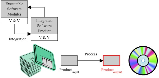
The Waterfall Model is the �classic software life cycle model�. This model was the only widely accepted life cycle model until the early 1980s. The waterfall model represents the software lifecycle as a series of �Products and Processes�. Each process takes the product as input and transforms this product and produces another product as output. Then the new product becomes the input for the next process. The detail overview of the Waterfall model will be discussed in the below sections.
The Waterfall model is a popular version of the systems development life cycle model for software engineering. Often considered the classic approach to the systems development life cycle, the waterfall model describes a development method that is linear and sequential. Waterfall development has distinct goals for each phase of development. Imagine a waterfall on the cliff of a steep mountain. Once the water has flowed over the edge of the cliff and has begun its journey down the side of the mountain, it cannot turn back. It is the same with waterfall development. Once a phase of development is completed, the development proceeds to the next phase and there is no turning back. The advantage of waterfall development is that it allows for departmentalization and managerial control. A schedule can be set with deadlines for each stage of development and a product can proceed through the development process like a car in a carwash, and theoretically, be delivered on time. Each phase of development proceeds in strict order, without any overlapping or iterative steps. The disadvantage of waterfall development is that it does not allow for much reflection or revision. Once an application is in the testing stage, it is very difficult to go back and change something that was not well-thought out in the concept stage. Alternatives to the waterfall model include joint application development (JAD), rapid application development (RAD), synch and stabilize, build and fix, and the spiral model [23].
Figure 22: Waterfall Lifecycle
7.3 Waterfall model characteristics The below table represents the processes and products of the Waterfall Model.
Table 2: Waterfall Characteristics Notice that the output product on the right becomes the input product on the left of the process at the next lowest level. The general formula for describing the transformation of products by processes can be written as follows:
Each product is represented by a grey box and each process is represented by a solid arrow connecting the boxes. In addition to the six processes and seven products that make up the Waterfall Model, several other important development activities and characteristics are represented in the model. One of these activities is �Testing�. �Inherent in every phase of the Waterfall Model is testing. Testing is not a separate phase to be performed after the product has been constructed; it should not be performed only at the end of each phase. Instead...testing should proceed continuously throughout the software process." Testing actually involves two steps: verification and validation. Verification is substantiating that the software has been transformed from one form into another as intended with sufficient accuracy. For example, the design process transforms the design specification document into the executable software modules. Verification in this case is determining that the software modules really are the entities that the design document describes. Verification answers the question "Are we building the software right? � Validation is substantiating that the software functions with sufficient accuracy with respect to its requirements specification. Using the same example as before, validating the executable software modules is determining that they behave as described in the requirements specification. Validation answers the question "Are we building the right software? � Testing involving verification and validation should be conducted in parallel with the development of the software product. In order to represent the testing activity as an ongoing process, the V&V boxes appear under each product of the Waterfall Model.
One important characteristic of the Waterfall Model is the iteration arrows that join the processes together. These arrows show how the development of one product can influence the development of previous products. A good example of this is the programming process loop. In the diagram below, notice how the programming process and the accompanying iteration arrow form a loop between the design specification document and the executable software modules [22].
Figure 23: Programming Process Loop It is possible that design flaws will be revealed during the programming of the software. When this happens, the design specification must be changed to reflect the correction, these changes must be tested, and finally the new design must be entered into the programming process again. This loop is repeated for all the design flaws that are discovered during programming. Notices in the complete Waterfall Model diagram, the iteration arrows connect all the processes with the exception of the delivery process. Like the programming process, requirements engineering, design, and integration are all iterative processes that involve progressive refinement of the resulting product. Another important characteristic of the Waterfall Model is the maintenance arrows which connect the delivered software product to the various other products in the life cycle. Remember that any changes made to the software product after delivery is considered as maintenance. A small change such as the correction of a programming error may only require a change in the code of the software. These types of changes are represented by the arrow connecting the delivered software product with the executable software modules. Other changes such as the addition of new functionality require a change in the requirements specification of the software. These types of changes are represented by the arrow going to the Changed Requirements product. Notice that a change in the requirements affects almost the entire lifecycle since these requirements become input to the design process and so on. Finally the dashed areas shown in figure 22 represent the maintenance phase of the life cycle. During which the software product continues to evolve through changes and improvements.
The Waterfall model begins with the �Requirements Engineering� process, which takes the communicated requirements as input and produces the �Requirements Specification Document� as output. The main purposes of this Requirement Engineering process are:- � Identifying the real needs of the client. � Uses Rapid Prototyping � Requirement specification is commonly used as a contract between the client and the developer
Figure 24: Requirement Analysis Along with the communicated requirements from the customers, the requirement phase also includes a detailed �Market Research� which evolves market requirements also. Together the communicated requirements and the market requirements finally evolve the �Requirement Specification Document�.
Market research is nothing but surveying the communicated requirements area in the market in which a product or service is offered, which are done to determine the cost of doing business, any competition, potential sales, etc. It has a broad scope and includes all aspects of the business environment. It results in answering questions about the following that make up the business environment:- � Competitors, � Market structure, � Government regulations, � Economic trends, � Technological advances, � and numerous other factors
After investigation about the competitors, market structure, economic trends and technological advances produces the �market requirements document�.
In this project �Design and Implementation of a Media Entertainment System running on a Carputer� the detail market research summarises some market requirements also. Many companies and research scholars all round the world involved in similar kind of project since 2 year which are already discussed in detail in chapter 4, but still customising the product to a user friendliness status are still in vain. Many people have problems in integrating the product in to the automobile dashboard and also facing problems in using a standard input device. All these results from market research phrases the �Market Requirements Document� along with the communicated requirements from the client.
Requirements analysis should also consider the technology research, which states the current trend about the product development. It holds good for both the hardware and software. Depending upon the technology research the company�s development strategies has been fixed in order to reduce the development process time and optimise the product release to the market. Sometimes the product development strategies have been fixed with the communicated requirements itself.
Rapid prototyping is commonly used for requirements engineering. It demonstrates the functionality of the software product to be developed. It is used to conduct experiments to identify the client�s real needs [19].
Figure 25: Rapid Prototype Rapid prototyping is very useful to Check the usability of the hardware and software, � Get feedback from the customer, � Promote further product requirements. The below figure shows the software prototype model:-
Figure 26: Prototype of the Kiebel Car Media Configuration Window
Figure 27: Inifile of Kiebel Car Media
Figure 28: Prototype of Kiebel Car Media Main Window
Figure 29: Software Prototype of Kiebel DVD Player
Kiebel Car Media prototype has two main forms � Main window & � Configuration Window
Main Window: The main window has four buttons used to launch some applications like GPS navigation software, DVD Player, Music Player and Video Player. All the paths needed for this button to launch the application will be stored in an INI file. Configuration window is used to record the data�s to the INI file. When the user press the button using a remote control or a mouse the software will launch the application depending on the path details from INI file.
Configuration Window: The configuration window mainly used to record the entire configuration data�s needed for the Kiebel Media Car software. It has text fields and buttons, using the button to browse the system the configuration data�s can be passed to the text field and then by clicking on the SAVE button will store the entire configuration data�s to the INI file.
Kiebel DVD Player prototype has two main forms � Main window & � DVD Panel
Main Window: The DVD Player has a video window which shows the movie. The whole system has been developed using a visual component library pack called �DSPACK� for Delphi 7.0 since the communicated requirements specified the product development strategy as Delphi 7.0. This window has a filter graph which gets the stream to be played.
DVD Panel: This Panel has a customised skin will all the media buttons present in it. This has been developed using a visual component library called �CoolForm� for Delphi 7.0.
As a result of this process the customer refined the requirements to modify the configuration window and main window so that the whole software is generalized for any application use. The main idea behind this refinement is that the customer can use their own name for the buttons in the Main form. All the configuration details will be updated and discussed in implementation section. Finally the requirements are record in a formal document called �Requirements specification document� or �External Specification Document�. This document commonly serves as a contract between the client and the developer, by which the final product is tested for acceptability.
The design process takes the requirements specification document or the external specification document as input and produces the design specification document or internal specification document as output.
Figure 30 : Design Structure
The design specification is commonly designed in multiple stages such as preliminary design, interim design and critical design. The design is gradually created through these stages. Sometimes these stages are also called High-Level or Architectural design and Low-Level or detailed design. The requirements specification document or external specification document states what the software must do and the design specification document or the internal specification document states how the software will do it. Most of the software design phase deals with high level or architectural design.
Software architecture forms the backbone for building successful software-intensive systems. Software Architecture largely permits or precludes a system's quality attributes such as performance or reliability. Architecture represents a capitalized investment, an abstract reusable model that can be transferred from one system to the next. Architecture represents a common vehicle for communication among a system's stakeholders, and is the arena in which conflicting goals and requirements are mediated. The right architecture is the linchpin for software project success. The wrong one is a recipe for disaster. From the external specification document there exists two solutions to implement a software architecture model. First one implement the DVD Player as a separate �exe� package and the second one implement the DVD player as an embedded �dll� file with the software. Later on discussion the former one has been chosen for effective programming which makes the project life cycle shorter.
Figure 31: Software Architecture Model
7.5.2 Unified Modelling Language (UML) The Unified modelling language is a graphical language for specifying, visualizing, constructing, documenting the artefacts of the software system. It is defined as easy to learn but semantically it is considered as a rich visual modelling language. It provides flexibility for applying different processes. It also enables model inter changeability and defines repository interfaces. The basic building blocks of UML are:- � Model elements (Classes, interfaces, components, use cases etc.,) � Relationships (Associations, dependencies, generalization etc.,) � Diagrams (Class diagrams, use case diagrams, interaction diagrams etc.,) The UML model of the Kiebel Car Media and the Kiebel DVD Player is shown in the below figure 32 and figure 33 respectively.
Figure 32 : UML model of Kiebel Car Media
Figure 33 : UML model of Kiebel DVD Player
Finally the high level or the architectural model along with the designs designed in unified modelling language is record in a formal document called �Design specification document� or �Internal Specification Document�. This document commonly serves as an input to the developers to proceed with the implementation phase which holds both the programming and the integration process.
In engineering and computer science, an implementation is the practical application of a method or algorithm to fulfill a desired purpose. For example, one might create a computer program that sorts a list of numbers in ascending order. To do so, one would implement a known method of sorting [21 & 24].
The programming process takes the internal or detail design specification document as input and produces the executable software modules as output. Since most software is tremendously complex, it is decomposed into several largest to manage the complexity. Different teams of people may be assigned to develop different modules. Later these modules will be integration and tested for the release of the product. All these process will be done by the configuration management department which management plays a critical role in the programming of the software modules.
Figure 34: Programming Process All the programming has been implemented in object-oriented language Delphi 7.0, since this programming language is the company strategy which has been specified in the communicated requirements. The details about the source code of the Kiebel Car Media and the Kiebel DVD Player are shown in Appendix A and Appendix B respectively.
The Integration process takes the executable software modules as input and produces the integrated software product as output. Integration testing plays an important role to ensure that the product is integrated successfully.
Figure 35: Integration Process Here to implement the integration process the software �Install Shield Express� has been used since it has been specified in the communicated requirements. This product is very easy and user-friendly to integrate all the executable software modules in to one single executable file. Features like license agreement customized banner or image of the company can also be included using this software. Options like automatically indicating the end user about new updates can be implemented during this process. Various installations like single executable, CD-ROM version or install from the web can also be created for customized needs. Reports can be created as a log file after the build process has been completed, which is very useful while updating the software version.
The life cycle of the software install shield is shown in the below figure.
Figure 36: Lifecycle of Install shield software 78
Software testing is a process used to identify the correctness, completeness and quality of developed computer software. Actually, testing can never establish the correctness of computer software. It can only find defects, not prove that there are none. There are a number of different testing approaches that are used to do this ranging from the most informal ad hoc testing, to formally specified and controlled methods such as automated testing. The quality of the application can and normally does vary widely from system to system but some of the common quality attributes include reliability, stability, portability, maintainability and usability. Software testing may be viewed as a sub-field of software quality assurance but typically exists independently (and there may be no SQA areas in some companies). In Software Quality Assurance, software process specialists and auditors take a broader view on software and its development. They examine and change the software engineering process itself to reduce the amount of faults that end up in the code or deliver faster [25]. A problem with software testing is that the number of defects in a software product can be very large, and the number of configurations of the product larger still. Bugs that occur infrequently are difficult to find in testing. A rule of thumb is that a system that is expected to function without faults for a certain length of time must have already been tested for at least that length of time. This has severe consequences for projects to write long-lived reliable software. One of the common misunderstandings of software testing is that it is performed by an independent group of testers after finishing the software product and before it is shipped to the customer. But this approach leads to the common effect that the test team is used as project buffer to compensate project delays. Additionally the earlier a defect is found the cheaper it is to fix I [21]t.
In software development, testing is usually required before release to the general public. In-house developers often test the software in what is known as 'alpha' testing which is often performed under a debugger or with hardware-assisted debugging to catch bugs quickly. It can then be handed over to quality assurance staff for additional testing in an environment similar to how it was intended to be used. This is often known as the second stage of alpha testing [21].
Following that, limited public tests known as beta-versions are often released to groups of people so that further testing can ensure the product has few faults or bugs. Sometimes, beta-versions are made available to the open public to increase the feedback field to a maximal number of future users [21].
There are companies that introduced the so-called gamma tests, which means feature-completed, but the software did not run through all the in-house quality checks. Some cynics refer to software release as "gamma testing" [21].
7.7.5 Software Testing Activities Some of the testing activities that are commonly used in the software industry to optimise the defects are listed below. Each and every testing activity is for specific purpose of testing [21]. � Unit testing � Integration testing � System testing � Regression testing � Load testing � Performance testing � Stress testing � Security testing � Installation testing � Usability testing � Stability testing � Authorization testing � User acceptance testing & Conformance testing Our project mainly deals with �Stress Testing�, since which has been specified in the communicated test requirements.
Stress testing is a form of testing which is used to determine the stability of a given system or entity. It often involves testing something beyond its normal operational capacity in order to observe the results. For example, a web server may be stress tested using scripts, bots and various denials of service tools. Medical context: Cardiac stress test is used mostly commonly to identify problems with blood flow to the heart muscle, sometimes other issues. Generally stress testing is nothing but testing the software under stress that is abnormal operational conditions. This can be done by automation process. Test Complete 3.0 is a tool used here to automate the testing process. The below table3 and table 4 shows the test cases of Kiebel Car Media and Kiebel DVD Player respectively.
Table 3 : Test Cases for Kiebel Car Media
The use of software to control the execution of tests, the comparison of actual outcomes to predicted outcomes, the setting up of test preconditions, and other test control and test reporting functions.The use of technology, such as capture/playback and data comparison, to enable test scripts/cases to be developed and executed (potentially in an unattended or off-hours mode). �TestComplete 3� is the automation tool here to test the developed Delphi executable files. AutomatedQA the company which introduced Test Complete has repeatedly shocked the Quality Assurance world by offering a full-featured testing and debugging solutions for prices that are fractions of the cost of "the big names TestComplete 3 adds HTTP load, stress and scalability testing, distributed testing and improved unit testing to its already formidable list of features. As the name implies, TestComplete is AutomatedQA's complete application testing system offering automated functional, unit, regression, distributed and HTTP performance testing in one easy to use and totally integrated package. TestComplete allows you and your team to implement comprehensive software testing strategies, �automating the non-automatable� for maximum ROI (return on investment). The recorded test scripts based on the created test cases produce the result and its causes if fails. This result can be viewed in a browser or inside Test Complete 3.0. A sample result log is shown in the figure 37. The recorded test scripts can be found in Appendix C. Also there is a movie file which shows how the testing process has been done from the recorded scripts. The movie file �Kiebel Car Media Testing� can be found in the attached CD-ROM.
Figure 37: Test log from TestComplete 3.0
7.8 Delivery & Maintenance Process The delivery process takes the integrated software product as input and produces the delivered software product as output. Acceptance testing is commonly conducted by the client to ensure that the delivered product meets the requirements specified in the contract. Once the client accepts the delivery, the software product is installed and used.
Figure 38: Delivery and Maintenance Process -1
Figure 39: Delivery and Maintenance Process-2 Every successful software product goes to an evolution which requires changes to the software product after its delivery. This evolution is commonly represented by a software version number. Changes may be required for variety of reasons such as fixing identified bugs, providing new functionality, adapting the software to new technologies, or porting the software to new platforms. These changes are called �Software Maintenance� represented by the dashed areas in the life cycle figure. Software Maintenance resolves in the modification of the software in different life cycle products from changed requirements to executable software modules.
Figure 40: Delivery and Maintenance Process-3
By the end of my master thesis, the development of the whole media entertainment system along with DVD Player software has been developed. Several testing process were done to ensure the reliability of the software, 95% of the project testing were successful and the remaining 5% of the tests has to be done on the hardware. The Graphical User Interface prototype acts as a good bridge between the developer and the client. It proves its user friendliness and it was very helpful for further improvements in requirements. The successful architectural designs were helpful to finish the development in time which made the project life cycle shorter. The project is extendable with various other functionalities with the help of the database in future due to its flexible architecture. Generally the software proves its usability with a well customized user interface and plays as a low cost solution for all automobile customers.
[Can03] Marco Canto. Mastering Delphi 7.0, Sybex Inc., USA, 2003. [1] http://tekgems.com/Products/creative-multimedia-remote-cimr100.htm [2] http://www.xenarc.com/product/cp1000.html [3] http://www.thisstrife.com/carproject/ [4] http://www.pricepc.com/html/carpc.php [5] http://www.mp3car.com/ [6] http://www.letscommunicate.co.uk/ [7] http://home.debitel.net/user/incar-media/incar/in-car-auto-multimedia.htm [8] http://www.delphipraxis.net/ [9] http://homepages.borland.com/torry/ [10] http://www.torry.net/ [11] http://www.delphipages.com/ [12] http://www.csd.net/~cgadd/delphi.htm [13] http://www.greatis.com/delphi/ [14] http://www.swissdelphicenter.ch/torry/ [15] http://delphi.helli.de/ [16] http://www.paranoia.clara.net/ [17] http://www.geocities.com/~franzglaser/tp.html [18] http://www.andrew.cmu.edu/course/46-939/notes/SoftLifeC.PDF [19] http://www.dacs.dtic.mil/techs/prototype/DACS-Prototype.pdf [20] http://en.wikipedia.org/wiki/Software_development_process [21] http://www.nationmaster.com/encyclopedia/ [22] http://courses.cs.vt.edu/~csonline/SE/Lessons/Waterfall/ [23] http://c2.com/cgi/wiki?WaterfallModel [24] http://en.wikipedia.org/wiki/Implementation" [25] http://www.nationmaster.com/encyclopedia/Software-testing [26] http://www.automatedqa.com [27] http://www.udsl.com/
|
||||||||||||||||||||||||||||||||||||||||||||||||||||||||||||||||||||||||||||||||||||||||||||||||||||||||||||||||||||||||||||||||||||||||||||||||||||||||||||||||||||||||
This site was last updated 10/10/04